Pressure loss is the consumption of the available pressure. Each equipment item (mixing valve, hose-spray assembly, pipe, elbow, ...) consumes a part of the available pressure.
This consumption varies according to the flowrate, hence the supply of pressure loss curves by manufacturers.
Thus, the pressure loss of a mixing valve varies considerably according
to whether drawing up or looping is involved. In an installation, one always adds the total of the pressure losses which it contains, in order to verify that the residual pressure will
always be equal or superior to 1 bar.
Average :
Mixing valve : 0.8 bars, free ;
0.4 bars, in looping.
Hose-spray assembly: 0.4 bars.
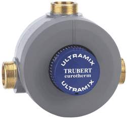
At the entrance of a building or house, the water pressure fluctuates between 3 and 5 bars ; generally, Whether or not it is equipped with a thermostatic mixing valve, a good installation must have balanced pressures on both fluids. WATTS Eurotherm manufactures a complete range of pressure reducing valve for this purpose. Minimum service pressure :__________________0.5 bars Pressure difference between hot and cold :_______1.5 bars • Check that the time-delay is the right quality and does not cause water-hammers (closing which is too abrupt). • In case of a water-hammer, the membrane may be damaged, causing the regulation to stop (the mixing valve is then impossible to adjust). • To operate properly with a WATTS Eurotherm mixing valve, a looping must include the following elements : - A circulating pump This pump must be properly calculated: temperature drop of 5°C between the mixing valve outlet and return. - A maximum speed of 2 m/sec, particularly after the points of use on the return. - The return pipe diameter must not be less than that of the mixed water outlet by more than two sizes. - Two micrometric adjustment valves. - Four non-return valves : two installed normally on the cold water inlet of the hot water production and the mixing valve + two installed after the micrometric valves on the loop return. - A water-hammer arrester, in case time-delay taps are used. - The mixed water return must absolutely be sent back at two points : - Approximately 80% of the flow on the cold water pipe of the mixing valve ; - Approximately 20% of the flow to the cold water inlet of the water production or on the storage medium if there is a connecting point. Adjustment to be completed according to temperature drops. • Maintenance operations. Temperature Adjustment with a circulation loop - Lubricate the control pins. Check and eventually replace the O-rings every 18 months. - Brush, clean the cartridge and remove the scale every : - 18 months for a 14 °DH - 12 months for a 18 °DH - 6 months for a 22 °DH (NB: 1 °DH = 1,78 French °TH) - When refitting the cartridge, check the condition of its seat and, if necessary, clean it ; • Operations subsequent to maintenance or stoppage - Redo the calibration. - If the temperature obtained after calibration is not constant, check that the O-rings and filters are at the same height. - If one of the two water lines does not come in, check that the valve-filters have been refitted in the right direction. The brass cone which acts as a valve stop must be fastened via the top. - Check that refilling with water has not caused an abrupt influx of sand and other waste matter. Implementation The operating simplicity of WATTS Eurotherm mixing valves results from their ease of implementation and the unparalleled quality of the result. The supply must correspond to the desired flowrate or to the diameter of the mixing valve’s inlets. The hot water storage tank must be sized according to use. Dynamic pressures (water pressure, tap open) must be 3 bars in order to obtain the best regulation at the best flowrate (generally, the static pressures which are indicated are higher than the dynamic pressures). The flowrates which appear in the tables or curves are in fact always given for dynamic pressures. It is necessary to include isolation valves at the inlets and at the outlet of institutional mixing valves. A WATTS Eurotherm mixing valve operates perfectly with a booster or a circulation loop.
Pressure
one assumes a pressure of 3 bars.
WATTS Eurotherm recommends a service pressure of less than 10 bars and, if possible, between 2 and 4 bars.
(1 m per 100 m of piping). The average manometric head noted in the recirculating pumps with the WATTS Eurotherm system is 4.50 to 6 m for six renewals/hour of the installation’s total capacity.
1. Turn off recirculation pump.
2. Open enough points of use on the mixed pipe to meet the minimum flow requirement of the thermostatic mixing valve.
3. Turn temperature adjustment to decrease or to increase the mixed outlet temperature.
NOTE: Please allow valve temperature to stabilize before making your next adjustment. Watts Industries recommends that a temperature gauge is installed on the mixed line and be checked at least monthly under normal flow conditions. The gauge must be installed at least 1,8 meter away from the thermostatic mixing valve.
4. When desired temperature is set, tighten the handle. Turn recirculation pump back on. Close open points of use.
On a model from the previous range, check that the control pin has been refitted.
The WATTS Eurotherm software package or the Daries chart provides all the useful information in a form which is very easy to use. In fact, the water speed must not exceed 2 m/sec. for good acoustic comfort, and 2.5 m/sec. in order to protect the installation from serious risks such as water-hammers.
At the same time, they indicate the pressure loss, that is, the dynamic pressure consumption corresponding to these flowrates.
Email : info@wattsindustries.fr
Site : www.wattsindustries.com